According to a certain captain W. De Rohan (1) existed the British Royal Navy of several categories of ships. The first class included ironclads like the HMS Minotaur and Warspite, “heavily armoured, for deep water fighting and short expeditions”. The second class included second rate ironclads on the broadside and also on Captain Coles’s system”with, by way of experiment, a monitor or two on the American system, having such improvements of modifications as the nature of these shores requires.” These ironclads should have at least quick veering power, being readily handed, have a little broadside as possible and be fast but also have a moderate fuel consumption. The third category consisted of sea-going ships in the real sense namely not just able to go to sea but also able to stay at sea without needing to seek shelter in case of storms in contrary to the British 6,000 ton ironclads at the time. De Rohan was thinking about cruising ships varying between 1,500 and 2,500 tons, able to develop a high speed, not or just lightly armored and a construction as basic as possible. Equipment was also to be basic as possible preventing the ship needed to retrun to her base for repairs. She needed to be äble to take care of themselves”. When not needed she used only her sails. Except for this type were gunboats, avisos, rams, torpedo boats etc. etc. of course still needed. De Rohan came with the following proposal fora second class warship. The original tex tis taken over.
The sketches of the designs he proposed were made back in 1861 and although handed over to the Admiralty and some friend never made public. De Rohan believe that a ship built according to this design adding some peculiar details not mentioned in the article would supply “one of the strongest, most effective and seaworthy crafts yet designed.”
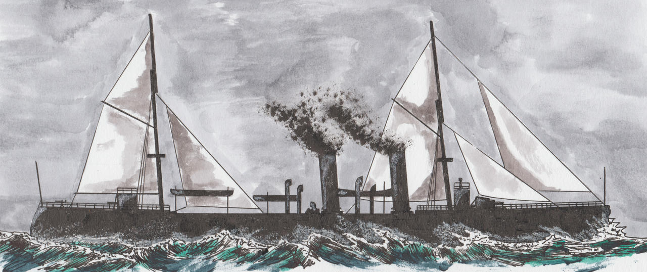
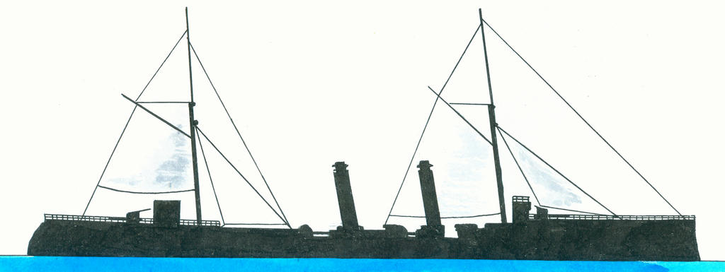
“Fig. 1 shows abroadside of the proposed ship under sail, her dimensions being, (say) length over all, 270ft.; extreme beam, 60ft. AA are telescopic lower, masts down, inside of which the upper halves are housed when needed; BB, battery, 8ft, high with a rake of4ft.from base ; CC, light bulwarks falling or shutting down inboard in action.

Fig. 2 shows the vessel ready for action; masts telescoped, bowsprit tripped, all spars, sails,&c., struck below deck,bulwarks down,and decks cleared fore and aft; DD, armour, tapering off in thickness to bow and stern; FF, a glacis at either end of battery from portsills down to deck, overlapping the sides of bulwark, for throwing off shot better; GG, diagonal bulkheads armoured, and extending from upper deck down to stem and sternpost; HH, lower hold divided off into compartments-the battery armour is fastened on vertically, and the side plating longitudinally.

Fig.3 shows a deck and battery plan. MM trend or incline of bulkheads GG from deck down to keels on, corresponding to, and flush out with, the sides of the ship. The battery is oviform, showing two equal segments of a circle, joined lengthwise by a common chord; its dimensions proportionably to the foregoing length and beam are-length outside, 100ft.; length inside, 95ft.; beam outside, 50ft.; beam inside, 45ft.; bulwarks, 2½ ft. thick at base,tapering up to 1½ ft and at top; top deck of battery plated with 3in. and having grating ventilators or hatchways; the plating of the battery, as of the ship, to be according to design and displacement of hull.The spars and sails shown in the engraving are, of course,for home service and short cruises; for sea-going and long cruises the spars and sails would be fitted to spread a large area of canvas, which the ship's great beam would enable her to carry easily. In action the ship is steered from a pilot-house inside the battery by chains leading down to fighting tiller between decks; the roof of the battery has hatchways,which are closed in action by grated or perforated hatches. End-on firing with the bow and stern guns is effected through a port on each side of the battery ends, shifting over to starboard or port as required on a transverse tramway, ports to close in loading by stoppers or bucklers.

Fig.4 of the engraving shows a body plan of an armoured ship-of-war. Extremebeam 60 ft.;width of battery, 60 ft.; roof of battery, 40 ft.;upper deck, 32f t.;water-line draught, 25 ft. or less; lower end of armour 9 ft. Below waterline. In this plan the present Government system is reversed, that is, the armour is inside and the woodwork outside. The inner armour of the Battery is necessarily thicker than that of the ship proper,and on the outside of the battery is also a thin armouring against small projectiles, &c. Thes hip shows a side or freeboard of 7 ft. clear from the waterline to upper deck, which with the inset of the battery sides,gives equal to 12 ft. Of clear side in an ordinarycraft. The bulwarks BB hinge down in board in action. The hull is of course caulked and coppered, as usual in wooden ships.
The following advantages are claimed for the designs shown in figs.1,2,3:
-First, the form of the battery harmonises, if it does not correspond exactly,withtheship'slines, and therefore its weight is distributed as evenly as can be over the strongest part of the ship's frame and bearings; its oviform or elliptical shape enables it to offer a better deflective target at all points than if square,and though geometrically speaking not necessarily so strong as a spherical battery would be,yet it has the advantage over the latter of having its weight better distributed,and, therefore, not only throwing less strain on a smaller area of the ship's frame,but tending as well to a more easy and considerably less motion in a seaway, two qualities that conduce so powerfully towards obtaining that grand desideratum. A steady platform.
-Second, clear decks, and no tophamper to foul the screw in action.
-Third, length, with great beam, a flat floor, and general form that will make her sit easy.
-Fourth, battery distinct from the forward and quarter decks, making, as it were a castle as well in heavy weather affording a refuge.
Fifth, the diagonal bulkheads from deck to keelson make, as it were, a ship inside a ship; and in engaging shore batteries in smooth water her show of side could be decreased y letting water into the hold compartments.(1)
Note
1. Captain W. de Rohan was in fact William Theodore Dahlgren (1820-1891 Washington, USA) and brother of the American Union Navy admiral John Dahlgren. In the 1840s he changed his family name for De Rohan from his mother's lineage. Being a soldier of fortune her served in navies worldwide like Argentina, Chile and Turkey and Italy (as admiral). Around 1867 he was active in international republican and maritime circles supporting Italian interests. Apprentice seaman since the age of 15. See for instance. George Jacob Holyoake. Bygones worth remembering. New York, 1905. Gutenberg Project and the website of the Ann Arbor District Library
Source
“Improvements in ships of War” in: The Mechanic’s Magazine and Journal of Engineering, Agricultural Machinery, Manufactures and Shipbuilding, vol. XVIL (new Series) 26 April 1867, p. 261.