Translate

Showing posts with label Designs. Show all posts

Tuesday, 15 September 2026

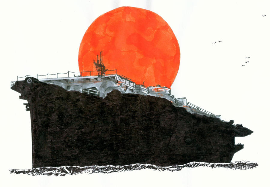
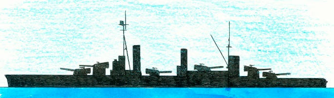
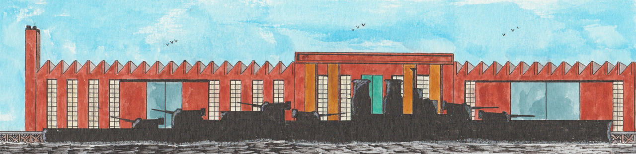
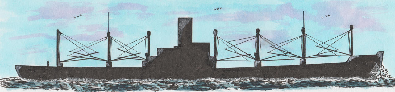
American simplified Ingall Shipbuilding Corporation C-3 type design

Type C-3 design©Warshipsresearch.blogspot.com

Bogue-class escort carriers©Warshipsresearch.blogspot.com

Dimensions 465.0 (between perpendiculars)-492.0 (over all) x 69.6 (moulded) x 42.6 (depth to shelter deck)-33.6 (depth to 2nd deck moulded) x 10.3 1/2 (light draught)-28.6 7/8 (draught loaded) feet. Gross ronnage (approx.) 7,940 tons, net tonnage (appox.) 4,700 tons, total deadweight tonnage 12,109 tons, displacement tonnage loaded draught 17,600 tons and 5,491 tons at light draught. Passenger accommodation for 6x2-12 passengers. Maximum trial speed 16.5 knots. Crago capacity 714,790 cubic feet, bale capacity 657,730 cubic feet. Total ship’s storage space 16,366 cubic feet and refrigerated cargo 38,040 cubic feet bale.

Preceded by Type C2 and succeeded by Type C 4. The United States Maritime Commission (MARCOM) designed the Type C3 in the late 1930s and which was to be a general purpose ship which could be modified for specific purposes. Between 162 were built between 1939-1946 and another 75 were completed using Type C3 hulls and engines but not as cargo ship. During the Second World War were several of the Type C3 ships converted into war ships as the Bogue-class escort carrier. 

Wednesday, 9 September 2026

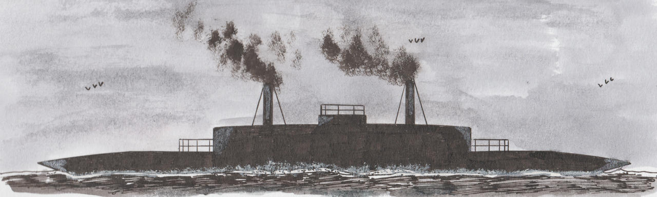
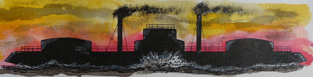
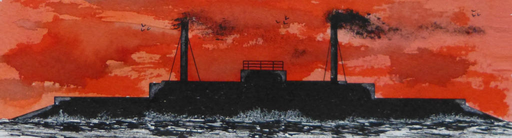
Design for a circular warship No. 3 by John Elder in 1868

©Warshipsresearch.blogspot.com

In the magazine The Artizan dated 1 July 1868 was a plate with figures and a small note published dealing with several designs for a ‘circular warship’ proposed by John Elder. He believed that such a ship with a widened beam could have a thicker and heavier armour and heavy guns compared with a ship of the common design and at the other hand a shallower draught and with a somewhat increased horsepower a comparable speed. The same year he read his paper Circular Ships of War, with immersed motive power for the United Service Institute in London, England. He executed experiments with his own construction and the common construction principles [the latter of a modern ironclad] including in all sorts of weather. It resulted in a draught around one-half of the draught of a common vessel allowing it to act in waters yet unaccessible. The power of rotation made it possible to act as a floating revolting turret or as a ram [like a gigantic circular saw).Diameter about 200 feet.

John Elder was a Scottish shipbuilder and marine engineer (8 March 1824 Glasgow, Scotland-17 September 1869 London, England). He worked for Randolph, Elder&Co., Glasgow, Scotland which became in 1886 the well known Fairfield Shipbuilding and Engineering Company.

The Russian rear admiral Andrei Alexandrovich Popov designed in 1869 the Charodeika-class monitor-class for the defence of the Dniepr-Bug Estuary and Kerch Strait. Popov used Elder’s ideas but by further widening the beam created a real circular ship and instead of a convex hull his design was flat-bottomed for a minimum draught. The armament was however not heavy enough and after several new designs was a design with a displacement of 6,151 tons, a diameter of 46.0 metres/151 feet and 4-27.9cm/11” guns approved. With too high building costs estimated was the design scaled down ending in the Novgorod laid down in 1871 with a displacement of 2,531 tons, a diameter of 30.8 metres/101 feet and 2-27.9cm/11” rifled muzzle guns.

Friday, 4 September 2026

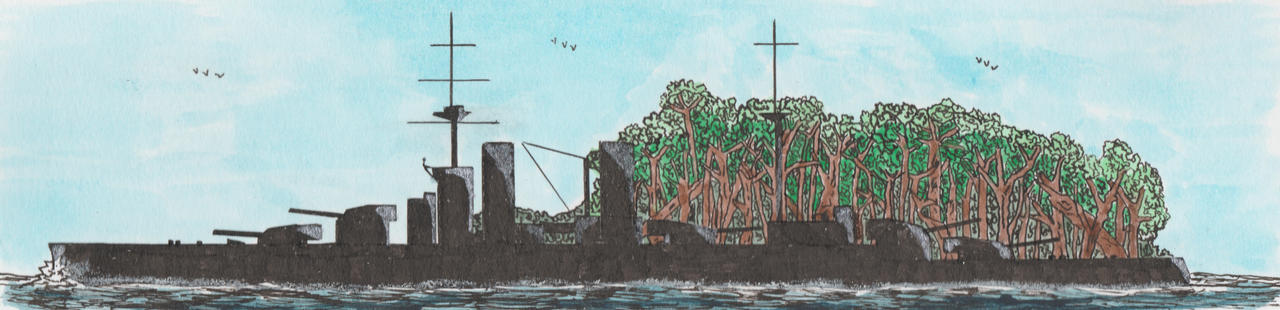
British design No. 764 of Sir W.G. Armstrong, Whitworth&Co. Ltd for a 31,500 tons battleship dated 11 April 1913

©Warshipsresearch.blogspot.com

A so-called stock design, not made for a specified navy. Dimensions 630 (between perpendiculars)-669 (over all) x 95 x 28.5 feet and a displacement of 31,500 tons. Main armament consisted of 5x2-38.1cm/15” cal 15 guns and secondary armament included 16x1-15.24cm/6” guns. Oil fuelled with a bunker capacity of 800-2,500 tons. Speed between 24-25 knots. The armour consisted oa a 13 “ thick bet, a middle belt of 13-6-4”, citadel and barbettes protected by respectively 6” and 10” thick armour. 

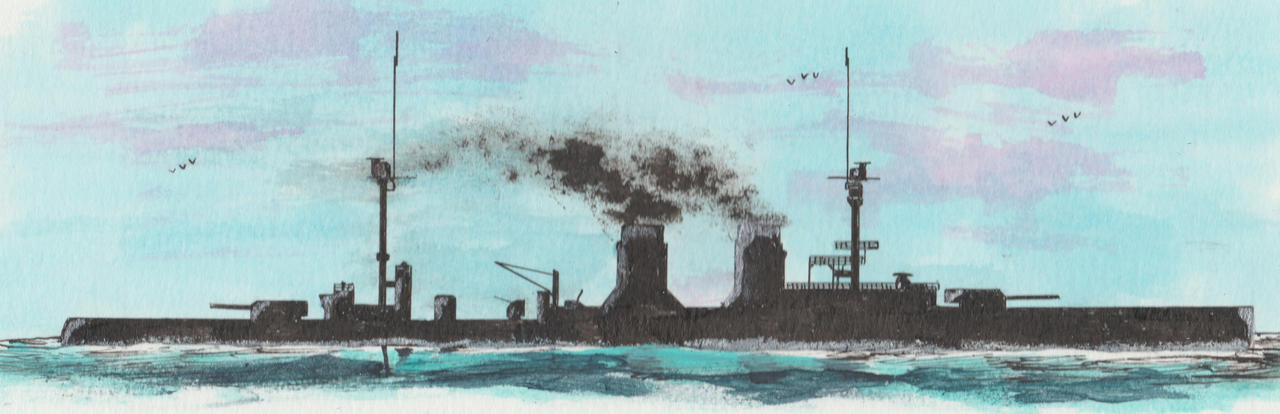
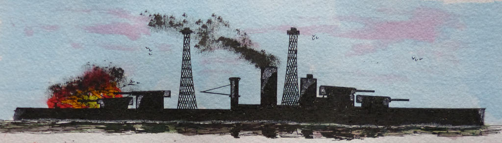
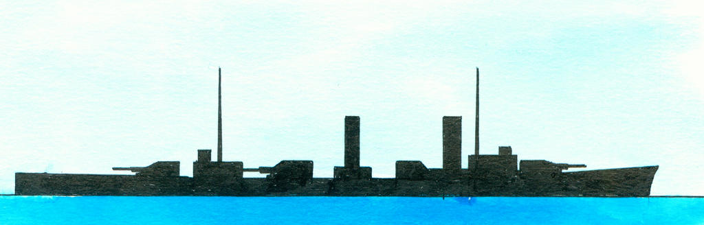
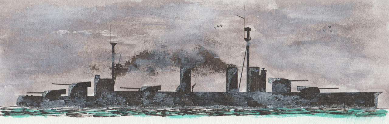
German battle cruiser study design GK 3531 dated 1918

©Warshipsresearch.blogspot.com

Dimensions 240 x 29,5 (maximum) x 9 (construction draught) and a displacement of 35,000 ton.

Armament 2x2-38xc cal 45 guns, 12x15 cm and 1 submerged bow torpedo tube.

Turbine propulsion,4 shafts, speed 31-32 knots, 16 coal and 15 oil fuelled boilers. 

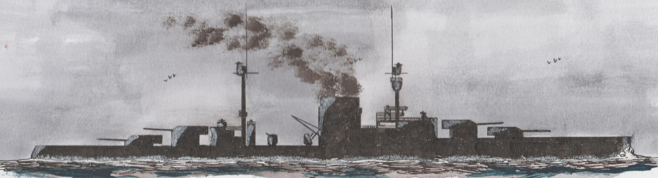
Austro-Hungarian design for a battle cruiser Project II dated June 1917

Displacement 30,000 tons with an armament of 2x3-38 cm guns L/45 guns, her secondary armament included 18x1-15cm L/50 guns. Speed 30 knots. Designed by Marinetechnisches Komitee (MTK). Never realized. 

Sunday, 30 August 2026

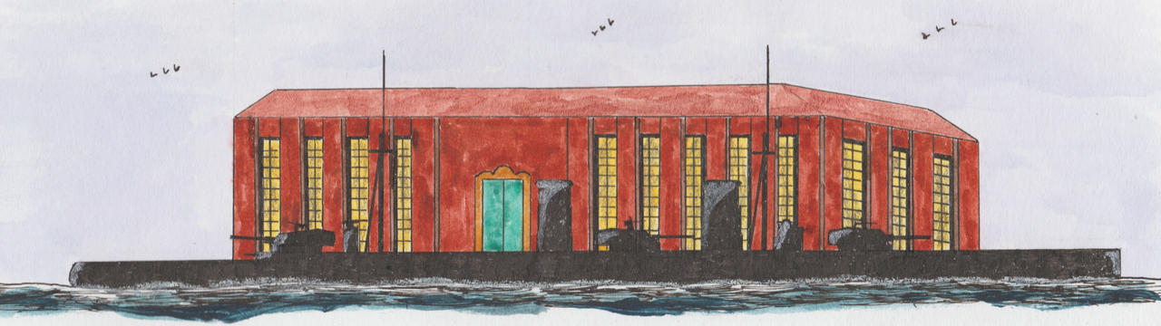
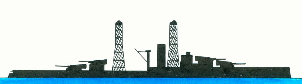
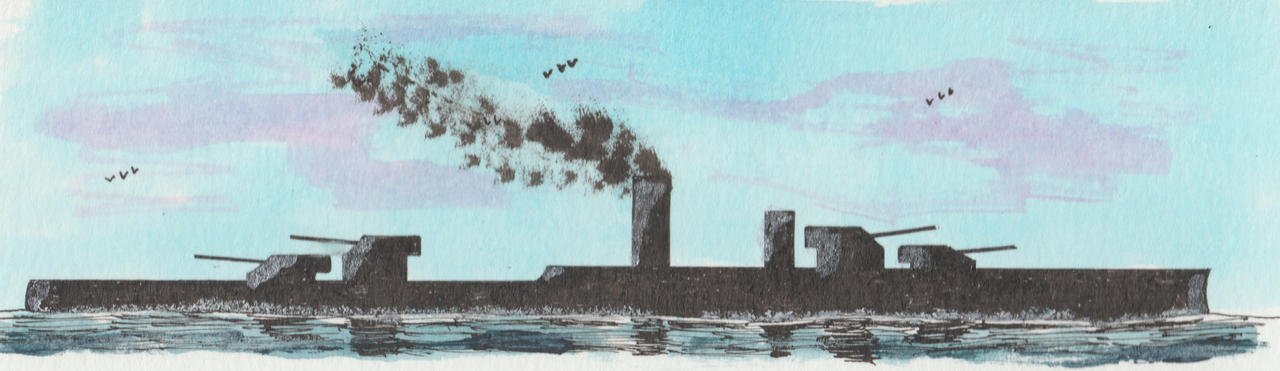
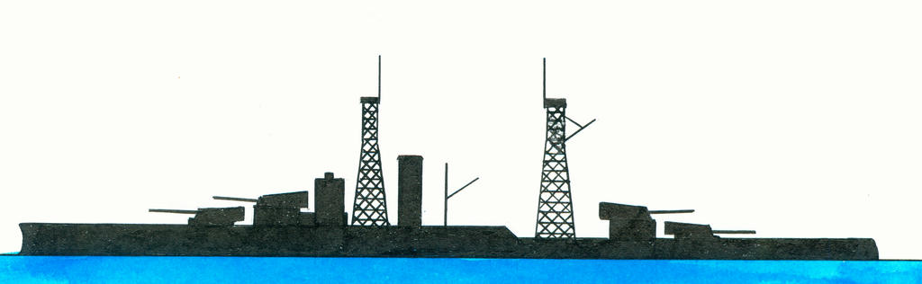
Preliminary design for the American battleship USS Pennsylvania (BB-38) dated 24 August 1912/3 September 1912

Nevada-class©Warshipsresearch.blogspot.com

Design dated 24 August 1912©Warshipsresearch.blogspot.com

Pennsylvania-class©Warshipsresearch.blogspot.com

New Mexico-class©Warshipsresearch.blogspot.com

Preceded by Nevada-class succeeded by New Mexico-class. Nearly final version of the design. In contrary to earlier preliminary designs was shifting the underwater side armour from the shell to an internal bulkhead. Contined the concept ‘all-or-nothing’ armour of the Nevada-class with increasing the thickness where really was needed and reducing elsewhere where less needed. USS Pennsylvania (BB38) and Arizona (BB39) were built to dis design.

Dimensions 600 (waterline) x 97’0 1/2”(outside armor) x 28’10” (mean draft) feet. Displacement 31,400 tons. Long. Coefficent ,629 (9 replaced in pencil by 7). Armament 4x3-35.56cm/14” B.K.R. guns, 22-12.7cm/5” quick firing guns and 4 submerged torpedo tubes.

Turbine propulsion, twelve boilers divided over 3 rooms, speed 21 knots. Range 8,000 nautical miles/10 knots.

Armour. Main side belt: widt etx. 17’4 5/8”, depth below water line 8’11 8/8, thickness 131/2-13 1/4-8”. Barbettes heavy part 13”, light part 4 1/2”. Turrets thickness port 18”, sides 9-10”, rear 9”, roof 5”. Conning tower proper, thickness 16”. Fire control 16”. Conning tower tube heavy 16”, light 6”. Uptake protection 13”. Protective deck, total 120#. Splinter deck, total thickness 80#-60#.

Weight summary normal condition:

Hull complete 13,390

Hull fittings 1,293

Protection 8,422

Steam engineering 2,399

Res. Feed 2/3 supply 209

Battery 1,658

Ammunition& 2/3 ordnance stores 1,310

Equipment&2/3 equipment stores, outfit& 2/3 stores 1,073

Oil fuel 2.3 supply 1,548

Margin 98

Normal displacement 31,400 ton.

Source

United States Navy Department. Bureau of Construction and Repair. Spring Stules 1911-1925. S-584-023

Saturday, 29 August 2026

Austro-Hungarian design for a battle cruiser Project IV dated December 1917

©Warshipsresearch.blogspot.com

Displacement between 32,600-34,000 tons with an armament of 3x2-38 cm guns L/45 guns, 18x1-15cm L/50 guns, 4-15cm L/50 dual purpose guns and 6 submerged 53cm torpedo tubes. Speed 30 knots. Horsepowe 112,000hp. Range 8,000 nautical miles/15 knots. Designed by Marinetechnisches Komitee (MTK). Never realized. 

Monday, 24 August 2026

Model of an anonymous floating battery gunboat dated around 1850

The figure head represents the head of a horse. Hull shows”a single row of widely spaced minute portholes”and amidships single superstructure with rounded ends with portholes in all sides. Single four-bladed propellor.

Source

Website Royals Museums Greenwich Collection search. ID SLR2704.

Proposal by William Haggett of the floating battery Prince of Wales A.2 dated 1862

Described in NPC9314 as “Gun deck over one vessel 70 guns with supplemental power fo extra speed and turning round”. Drawing NPC9315 is title ‘Battery with one vessel 70 guns” and shows “a combined deck floating battery, a single deck floating battery and the framing and plating”.Design of architect William Haggrtt from Sherborne, Dorset, England.(2)

Note

1. William Haggett (1808-1887), architect of profession and surveyot. Held some patents including Haggett’s Improved Method of Treating Metals&c. to increase their strength, filed 20 September 1859 and one dated 24 April 1862 for improvements in locomotive engines and carriages for railroads, tram and common roads.

Source

Website Royals Museums Greenwich Collection search. ID NPC9313-9314, See also NPC9315-9317-9318. 

Proposal by William Haggett of the floating battery Victoria A.1 dated 1862

Described as a combines three deck battery. Drawing NPC9310 mentioned a gun deck with 71 guns. Drawing NPV9311 illustrated what was possible if two ships with extra engines were combined: “Combination when more than 1 ship is employed with extra engines to give greater speed”. Drawing NPC9315 is title ‘Battery with one vessel 70 guns” and shows “a combined deck floating battery, a single deck floating battery and the framing and plating”. Design of architect William Haggett from Sherborne, Dorset, England.(1)

Note

1. William Haggett (1808-1887), architect of profession and surveyot. Held some patents including Haggett’s Improved Method of Treating Metals&c. to increase their strength, filed 20 September 1859 and one dated 24 April 1862 for improvements in locomotive engines and carriages for railroads, tram and common roads.

Source

Website Royals Museums Greenwich Collection search. ID NPC9310-9311-9312-9316. See also NPC9315-9317-9318.

Proposal by Peter Borrie for a 19th Century anonymous steam floating battery

Described as an improved safety iron twin steamship by engineer Peter Borrie, No. 3 Crescent, Minories, London, England.

Note

1. PeterBorrie (8 March 1802-South Latch, Abernyte, Perthsire, Scotland-10 January 1856 Middlesborough, England). Came in 1832 with the side connecting rod Borrie engine, designed by himself. Of Peter Borrie&Co., Tay Foundry, Dundee, Scotland producing marine engines for ships, parts of iron ships and locomotives, since 1840, went bankrupt in 1842-1843, apparently inventory sold in April 1846, established a shipyard at Middlebrough, England in 1853. Held a patent for a Safety Iron Twin Steamer dated 1850. Named Gemini was she suitable for transporting good, persons and cattle, mainly built of iron with two separate hulls placed side by side, with them them the paddlle box. At each end of this paddle box were deckhouses positioned. She was to serve on rivers and had a lenght of 157.5 feet, a beam on deck of 26.5 feet, with each hull being 8.5 broad and a space of 9.5 feet between them. If she was to serve at sea was her boam to be increased in proportion to length and the trade.

Sources

Website Royals Museums Greenwich Collection search. ID NPD0516 and 0517.

The Artizan, May 1844, p. 115

British proposal for an anonymous ironclad frigate with movable turrets in 1867

Made by Palmer’s Shipbuilding&Iron Co. Ltd., Laird Bothers Ltd. on 27 July 1867. Drawing NPC8886 mentioned “Comperative Design.”

Source

Website Royals Museums Greenwich Collection search. ID NPC8886-8887-8888-8889.

Saturday, 22 August 2026

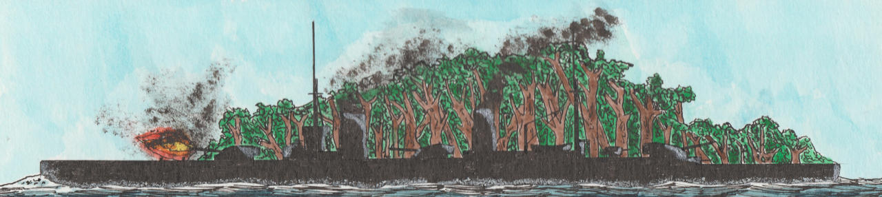
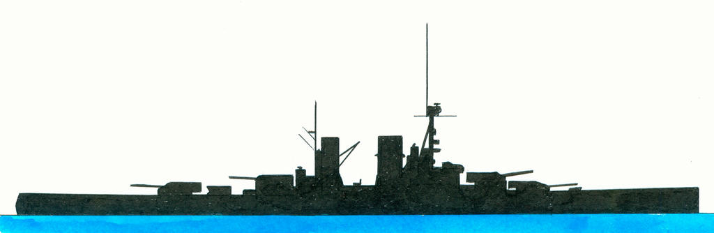
German battle cruiser study design GK 4542 dated 25 February 1918

Mackensen-class©Warshipsresearch.blogspot.com

GK 4542 design©Warshipsresearch.blogspot.com

Dimensions 240 x 33.5 (maximum) x 10 (construction draught) metres and a displacement of 45,000 tons. Armament 4x2-42 cm cal 45 guns, 12-15cm cal 45 guns and 1 submerged bow torpedo tube. Turbine propulsion with 4 shafts16 coal and 10 oil fuelled boilers, speed 28-30 knots. 

Thursday, 13 August 2026

German shipbuilding engineer Oswald Flamm and his designs of a submarine cruiser between 1921 and 1927

French submarine Surcouf©Warshipsresearch.blogspot.com

British submarine HMS X-1©Warshipsresearch.blogspot.com

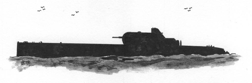
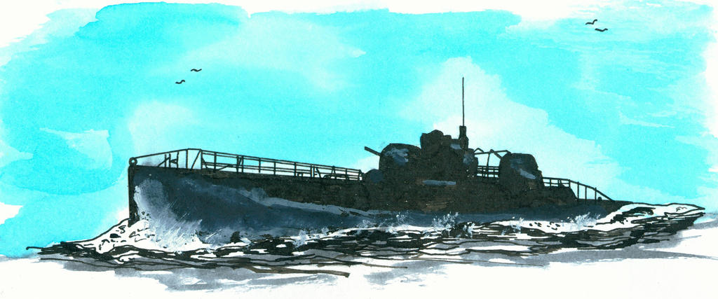
On the frontpage of the The Duisburger General-Anzeiger dated Monday 17 January 1921 was article published titeld Das U-Boot der unbegrenzten Möchlichkeiten [roughly translated the submarine of the unlimited possibilities]. The reporter wrote that thanks to the reseach of Flamm (1) naval war was to be changed radically. The size of the submarine was no longer limited and to be armed with armor protected heavy guns. Flamm developed a new stapbility principe after many years of intensive research allowing him to build much larger submarines. At that moment he designed an amored U-boot cruiser of 1,433 tons with a 35mm thick armor weighing 134 ton and an area of 750 square metres. At both ends of the deck was an armored gunturret positioned with a 10.5cm gun. Also on deck were rotatable torpedo tubes mounted, and under deck were fixed tubes built-in. Surfaced speed was 17.5 knots. Nearly completed were the plans for a submarine of 4,870 tons with a length of 100 metres. She was to be armed with 4 smaller or two 21cm guns mounted in 2 armored gun turrets like the earlier mentioned design. Speed was increased to 25 knots. Further more he was working on a concept for a submarine of 8,400 or 9,900 tons which was to develop a speed of 28 knots. She was to be protected by 6-7cm thich armor plates and to be armed with four 21 or 24cm guns, again mounted in armored turrets.

The magazine Die Umschau volume 25 No. 6 dated 5 February 1921 p. 74 reported that Flamm, professor at the Charlottenburger Technischen Hochschule succeeded in designing a submarine which was armoured without negative effects for the stability while diving or submerged cruising. Until then was the danger of turning around the main objection against the use of armour. There were project drawings available for an armoured submarine cruiser of 1,443 tons volume content and with a speed of 17.5 knots. Patents were obtained in the United Kingdom, The Netherlands and Italy and negotiations went underway in the USA.

The Time Magazine (topic The Machine Age dated 4 February 1924) wrote that the Maschinenfabriek Augsburg-Nürnberg AG (MAN) made a model of a submarine cruiser of more as 7,000 tons and supplies. Interesting details are supplied: "The boat is heartshaped, point upward, with the keel in the groove of the heart, like an inverted V. The principal advantage is rapid and even submersion, the stability depending on the form and the distribution of pressure. It can submerge in 30 seconds without turning a degree, can cruise 20,000 miles and develop a speed of 23 knots an hour. It is 525 ft. long and 49 ft. wide, and carries large torpedo and gun armament."

The Karlsruher Tagblatt dated Wednesday 23 April 1924 published on page 6 an article dealing with the submarine cruiser war of the future which were without any doubt to become of the most dangerous weapons in a future naval war. USA, England and France showed signifant interest in building such submarines. An absolute independence of submarine support points excluded the submarine home base or an unlimited range as proposed in Flamms designs was yet not realized. He designed two twin boats namely a submarine cruiser of 7,067 tons and a submarine minelayer of 7,700 tons displacement. Both types had the same speed and diving qualities to able the boats to cooperate closely.

The submarine cruiser would have a length of around 403 feet. Deck and sides were heavily armoured against air attacks. The deck armament included 2-21cm guns and some 60 calibre guns met sufficient ammunition storage. In the First World War was the calibre maximum 40-calibre. In the bow and stern were 4 torpedo tubes fitted for which 45 torpedoes were carried. Until now was that just six torpedoes. The diesel propulsion delivered 30,000 allowing a surfaced speed of 22-23 knots possible. For submerged cruising was a 5,000hp electric engine available. Crew numbered around 100 men. Dive time 1 minute. Building time around 9 months and costs around 40 million mark.

The Australian newspaper Northern Star dated Saturday 10 January 1925 referred to an article recently published in Marine Rundschau dealing with the designs of Flamm. Despite his opinion that battleships and other types of surface warships were still indispensable, he thought that submarines ought to have a higher place in naval warfare in the future. Key word in his research was supreme importance of stability in submarines which he wanted to ssolve by adopting a new hull form. This form supplied a perfect stability while diving “and when running submerged, continues to steadniness of trim, and enables relatively enormous weights to be carried on the upper part of the hull.” As far as he known other navies depended for the stability of their 4,000+ tons submarine cruisers on ballast or deadweight to carry. If ballast was not used for assuring the staibility they should use his system of construction and which was patented world wide. Since 1919 he was doing intensive research in this matter.

One of his projects was a diving cruiser of 7,067 tons displacement fitted out with defensive armour with a weight of 614.5 tons and armed with turret guns, quick firing guns and torpedo tubes with a weight f 500,5 tons. The idea behind this design was ‘that such a vessel mounting one or more heavy guns in deck turrets and having its sides plated with armour, could rise to the surface and, with only its upper works showing, canonnade with deadly effect the unarmoured sides of an enemy dreadnought. The submarine itself would present an almost invisble target, and could only be hit by chance.”

The American magazine Popular Science dated 1927 reported that the French navy completed the largest submarine of the world with a tonnage of 3000 tons. This was the Surcouf (2). Flamm planned a much larger submarine cruiser which had a tonnage of 7,067 tons, a length of 403 feet and which was armed with 2-8” guns. The British Royal Navy had the X-1 (3) of 2,780 tons, a length 351 feet and which was armed with 4” guns and 21” torpedo tubes and able to remain 2.5 day submerged.

Notes

1. Oswald Flamm (30 July 1861 Düsseldorf, Germany-12 June 1935 Berling, Germany, Berlin) shipbuilding and -engine engineer. Played an important role in the German shipbuilding and was specialised in screws. stability and submarine building. He was according to Time Magazine (website Time.com) reponsible for a “series of revolutionary, non-patent designs for heavily armored, giant submersible dreadnought and u-boat cruisers between 1921 and 1930.”

2. Ordered on 4 August 1926, laid down by Cherbourg Arsenal on 1 July 1927, launched on 18 November 1929, commissioned ion 16 April 1935, refitted in 1941 and disappeared on 18 February 1942. Pennant N N 3 and designation number 17P. Displacement 2,926 (dead)-3,302 (surfaced)-4,373 (submerged) tons and as dimension 361 x 29.6 z 23.9 feet or 110 x 9 x 7.25 metres.

3. Laid down by HM Dockyard, Chatham, England on 2 November 1921, launched on 16 June 1923, completed on 23 September 1925, commissioned in December 1925, partof the reserve since 1930 and broken up on 12 December 1936. Displacement 2,820 (surfaced)-3,700 (submerged) tons and as dimensions 363.6 x 29.9 x 15 or 110.8 x 9.1 x 4.6 metres. Armed with 6-53.3cm/21” torpedo tubes in de bow and 2x2-13.2cn/5.2” guns.

Sources

Trove website Australian newspapers.

German Digital Newspapers Archive

Delpher.nl

New Zealand Historical Newspapers Papers Past

Japanse battleship design A 50 around 1911-1912

Kawachi-class. ©Warshipsresearch.blogspot.com

Design A 50. ©Warshipsresearch.blogspot.com

Fuso-class. ©Warshipsresearch.blogspot.com

Displacement 27,100 tons and as dimensions 570.0 (between perpendiculars) x 93.0 (extreme) x 29.6 feet. Speed 22 (36,000 shp)-23 (43,300 shp) knots. Normal coal bunker 1,200 capacity tons. Armament 5x2-35.56cm/14” 45 cal with 70 rounds each, 12-15.24cm/6” 50 cal, 10-11.9cm/4.7” 40 cal guns. 2-7.62cm/3” short guns and 4-53.34cm/21” submerged torpedo tubes. Armour consisted of a 30.48cm/12” (waterline) belt, a 1 1/8” thick protective deck and barbettes protected by 21.86cm/9”.

Source

Hiraga Archive ID 20260301

Wednesday, 12 August 2026

German shipbuilding engineer Oswald Flamm and his design of a submarine minelayer between 1924-1925

The Karlsruher Tagblatt dated Wednesday 23 April 1924 published on page 6 an article dealing with the submarine cruiser war of the future which were without any doubt to become of the most dangerous weapons in a future naval war. USA, England and France showed signifant interest in building such submarines. An absolute independence of submarine support points excluded the submarine home base or an unlimited range as proposed in Flamms (1) designs was yet not realized. He designed two twin boats namely a submarine cruiser of 7,067 tons and a submarine minelayer of 7,700 tons displacement. Both types had the same speed and diving qualities to able the boats to cooperate closely.

Some of these large minelayers were able to arrive within 24 hours secretly the Panama Canal or the Suez Canal. Their huge range was similar to the circumference of the earth and made it possible to leave their secrete base for a far away destination, do their job and return without the necessity of of a stopover. The submarine minelayer had a construction similar to that of the submarine cruiser. Instead of the guns and torpedo tubes carried shee around 1,000-1 ton or 2,000-500 kg mines with her. In the First World War was the maximum around 20 mines. Her only protection against an enemy attack was diving. The mines could be laid with mathematic accuracy with completely arbitrary intervals and the whole process was the commanding officer informed by automatic signals. Building time around 9 months and costs around 28-30 million mark.

The Australian newspaper Northern Star dated Saturday 10 January 1925 referred to an article recently published in Marine Rundschau dealing with the designs of Flamm. Despite his opinion that battleships and other types of surface warships were still indispensable, he thought that submarines ought to have a higher place in naval warfare in the future. Key word in his research was supreme importance of stability in submarines which he wanted to ssolve by adopting a new hull form. This form supplied a perfect stability while diving “and when running submerged, continues to steadniness of trim, and enables relatively enormous weights to be carried on the upper part of the hull.” As far as he knew other navies depended for the stability of their 4,000+ tons submarine cruisers on ballast or deadweight to carry. If ballast was not used for assuring the staibility they should use his system of construction and which was patented world wide. Since 1919 he was doing intensive research in this matter.

One of his projects was a submarine minelayer of 7,734 tons displacement able to carry with her 1,000 mines each with a weight of 1 ton. He stated that this design would be the most formidable in war. She would be more dangerous than an other project of him namely a submarine cruiser. The wide radius of action and the fact that she could stay for months at sea, high speed and large number of mines made her such dangerous.

Note

1. Oswald Flamm (30 July 1861 Düsseldorf, Germany-12 June 1935 Berling, Germany, Berlin) shipbuilding and -engine engineer. Played an important role in the German shipbuilding and was specialised in screws. stability and submarine building. He was according to Time Magazine (website Time.com) responsible for a “series of revolutionary, non-patent designs for heavily armored, giant submersible dreadnought and u-boat cruisers between 1921 and 1930.”

Sources

Trove website Australian newspapers.

German Digital Newspapers Archive

Delpher.nl

New Zealand Historical Newspapers Papers Past
Tuesday, 11 August 2026

Japan interested in submarine designs of German shipbuilding engineer Oswald Flamm according to the Dutch magazine Marineblad dated 1925 No. 2

An item referring to the German magazine Schiffbau dated 19 November 1924 reported that Japan was interessed in three types of submarines of which one of the Flamm type with a displacement of 3,000-7,500 tons. Ocean going and protected against gunfire, aircaft bombs and submerged weapons. To be armed with at least 2-20cm guns, to carry 40 torpedoes with her and with a range of around 25,000 nautical miles. The living accommodation on board allowed a stay of several months at sea. The submarines were such to be constructed that a large diving depth would become possible. This magazine wrote that Japan received drawings from Flamm for a 7,000 tons armoured submarine armed with 2-20cm guns. However the editors doubted if Japan would spend such high building costs for a experimental submarine. On the other hand were rumors that Japan was building of one or more submarines of 3,000 tons displacement conform Flamms’ stability principles make it possible to mount heavy weights on deck without disturbing the stability while submerged. 

Saturday, 8 August 2026

British Armstrong Whitworth design No. 740 of a stock battleship dated April 1912

Design No. 740©Warshipsresearch.blogspot.com

Japanese battleship Fuso©Warshipsresearch.blogspot.com

Displacement 31,500 ton and as dimensions 650 (between perpendiculars)-685 (over all) x 96 x 31.25 feet. Armament consisted of 6x2-35.56cm/14 inch 50 cal guns, 16x1-15.24cm/6” 50 cal guns and 4 submerged 53.34cm/21” torpedo tubes. Estimated speed 23 knots. Friedman (The British Battleship 1906-1940) and others claimed that this design was used as proposal for what became the Japanese dreadnought Fuso, laid down by the Kure Naval Arsenal on 11 March 1912. Japanese designers had at the time access to British information like files from Vickers dealing with double and triple gun turrets designs. Sie for instance the Hiraga archive. 

Thursday, 30 July 2026

Circular ironclads proposed by British commander G.H.U. Noel in 1876


Sharpened edge of the circular ironclad Noel proposed

Proposal No. 8 of John Elder in 1868©Warshipsresearch.blogspot.com

Proposal No. 10 of John Elder in 1868©Warshipsresearch.blogspot.com


Model of circular floating battery by John Elder. National Maritime Museum Greenwich ID SL2545


Model of Russian Popovka Novgorod 1873. National Maritime Museum Greenwich ID SLR105

Major C. Field published in 1900 an article dealing with proposals for warships which were never realized. At that moment was in England series of types of warships settled built in batches. In the past was that quite different. Since the introduction of the French ironclad La Gloire launched on 24 November 1859 was choosen for a methof of constant experiments or as he wrote: “In some foreign navies this system of constantly trying to make a ship radically different to anything that has preceded it still goes on, notably in France.” And there were numerous proposals, ideas and even models of warships by naval engineers and/or officers, private inventors which never were realized. One example was a couple of a circular ironclads by commander Noel inspired by the Russian circular ironclads (monitors) or popovkas designed by rear-admiral Andrei Alexandrovich Popov (21 September 1821 Russia-6 March 1889 Russia) and built as the Novgorod (1871-1874) and Vice-admiral Popov (1874-1876). Both ships were to serve in the Black Sea and the Sea of Azov. Popov was not the ony one interested in circular ships, for instance John Elder published in  The Artizan, dated 1 July 1868 an article "Circular vessels of war" over the effects of widening the beam illustrated by several more or less circular ships. In the Transactions of the Institution of Naval Architects, volume XVIII, 1876, is an article published by E.E. Goulaeff, “On Circular Iron-clads”, p. 43-61 and in the discussie pointed Jamieson of John Elder&Co. Out that the late John Elder already in May 1868 read a paper dealing about this subject, discussed it officers of various governments included Popov and that Popov even visited Glasgow in 1868 probably to gett full details. Goulaeff said clearly in his paper that Popov came in early 1869 with his circular ships concept.

Field described the popovkas as”In almost every point they are a failure ant is not likely that anyone would now expect a circular ship to be anything else. Imagine the power necesssary to drive the unwieldy affair throught hthe water, and the impossibility of speed.”

Dealing with the proposal of Noel his comment was equal negative: “The ship in the picture gives one the impression of a gigantic Quoit, and is, in fact nothing more rga a flaoting redoubt. It is, of course, intended for coast dfenece, and nowadays, whe we have grasped the fact that we must defend our own coast, or that of our enemy puts it out of court at once. The twelve big guns that peer over the armoured breatsworks are so mounted that on being fired, they recoil below it to be loaded. The edge of the ship was to be a huge sharp steel ring, so as to slice into an enemy; she was to have three screws, and four keels.

Brassey, sir Thomas. The British Navy: its strength, resources, and administration, volume III, Part III, Opinions on the shipbuilding policy of the Navy, London, 1883 dicusses the value of circular ships like the Povkas. Commander Noel (p.496) pleaded for circular ironclads to get an efficient coast-defence fleet. For the Thames and South-coast harbors he suggested 4 ironclads 1st class of around 8,500 tons and 6 circlar ironclads 2nd class of around 5,000 tons be stationed at other harbours. His opinion is followed that by the famous Sir E.J. Reed (p. 99) who stated that “Fore special purposes some modified form might be prerable, but generally speaking, the circular form is the best for floating armor to protect an included space, and also for giving that equal all-round command with your guns which is so desirable at sea. Starting then with this circular armoured citadel, and wishing to propel it at speed, there are several ways in which we cam deal with it.” and “I believe the circular form is itself quite compatible with high speed, and certainlu it possesses very great and numerous advantages in other respects.” Reed published a paper “On Circular Iron-clads published in the Journal of the Royal United Services Institute for Defence Studies, volume 20, 1876. In the same journal is the Naval Prize Essay of Noel “On the Best types of War-Vessels for the British Navy” published. It was in this essay that Noel described his circular ironclad or floating fort proposal:

1st-class, about 8,500 ton, diameter of 210 feet, 12-30.48cm/12” 35-ton guns mounted on an imrpoved Moncreiff system behind a breastwork of 14” armor, 6 feet high and circular in form with a diameter of 100 feet, deck outside breastwork is curved downward toward the outer edge of the ironclad and plated with 3.5” iron, the under surface nearest to the dge plated with 3.5 armor. Edge protected by a steel rim of immense strength, sharpened to cut the bow of an attacking ship which wanted to ram her. Speed 10 knots. Weight armour breastwork 500 tons, upper surface of armoured deck 1,700 tons, under surface 450 tons, total weight same as that of HMS Devastation.

2nd-class, about 5,000 ton, diameter of 150 feet, 10-25.4/10” 18-ton guns mounted on an improved Moncreiff system behind a breastwork of 12” armor, 5 feet high and circular in form with a diameter of 80 feet, plating outside 3” thick. Weight armour breastwork 270 tons, upper surface of armoured deck 700 tons, under surface of edge 230 tins, total weight about 1,200 tons.

Sir Gerard Henry Uctred Noel (5 March 1845 Stanhoe, Norfolk, England-23 May 1918 Fincham, Norfolk, England) served in the Royal Navy between 1895-1915 ending his career in the rank of Admiral of the Fleet. He published in 1874 the prize essay “The Gun, the Ram and the Torpedo. Manoeuvres and tactics of a naval battle in the present day”.

Source

Field, major C., “Warships that have never floated”, The 1d Pictorial Magazine or The Penny Pictoral Magazine, No. 35, volume 3, week ending 3 February 1900, p. 435-438 . Edited by Charles P. Sisley. 

Saturday, 25 July 2026

A battleship like a kraken according to the newspaper Hawera&Normanby Star dated 8 December 1910

An item reported that the American major general Leonard Wood, Chief of Staff recently received a model of a battleship fitted out with huge arms like a devil-fish, able to walk over the bottom of the water. The ship called by the newspaper ‘a real leviathan” could “skim over the waves as lighty as a swallow and do the rest crawling on its hands and knees until it is under the middle of the opposing fleet. It then thrusts out hidden tentacles of steel and pulls the fleet to destruction.”Sadly enough was no more details supplied.(1)

Note

1. Leonard Wood (9 October 1860-7 August 1927), chief of staff of the US Army (22 April 1910-21 April 1914), military governor of Cuba (23 December 1899-20 May 1902) and governor-general of the Philippines (14 October 1921-7 August 1927).

Source

New Zealand historical newspapers. Papers Past